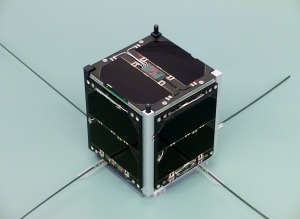
AO-73 (FUNcube-1) – Image credit Wouter Weggelaar PA3WEG
FUNcube-1 (AO-73) was launched into space two years ago on November 21, 2013.
We are delighted to be able to report that more than 900 stations, including many schools around the world, have received the telemetry from the spacecraft since launch. Our Data Warehouse is storing more than 750 MB of data from almost 1 million data packets. We are very grateful to everyone who has been contributing to the success of this mission. Please continue to keep the data flowing as it will provide a valuable resource for students in the future.
The stats continue – speeding along at around 17,500 mph, FUNcube-1, which had a launch mass of just 982 grams, has completed more than 10,500 orbits of the earth. This means a total distance travelled of more than 260 million miles.
All telemetry sensors continue to provide valid data, real time, whole orbit and high resolution channels alike. The flight code is really robust and we have only had three unexpected “events” since launch. Two of these we believe to have been caused by noise of the command receiver being incorrectly interpreted as a command and only one appears to have been caused by a RAM error. The battery and solar panels also continue to work perfectly and provide a very positive power budget.
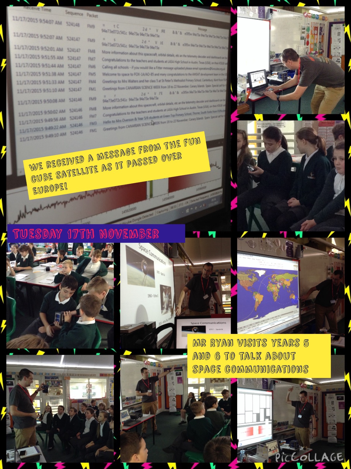
We have sent out many Fitter messages for school and other similar events. On November 17, 2015 there was a demonstration at Thorne Green Top School in Yorkshire. Here is a report from Dave Ryan EI4HT/M0GIW:

FUNcube-1 Educational Outreach – Thorne Green Top School in Yorkshire
Good Morning All
Firstly -thanks to all for your help, we had a great morning at Green Top and the highlight was FUNcube.
I started with a slide show talking about communications from cave paintings all the way up to smartphones, we looked at space communications and travel from Sputnik to Astra and Apollo to the Millennium Falcon! We spoke about satellites and how they are used every day and how we all got to watch “I’m A Celebrity” via Satellite last night from Australia.
I brought in lots of props too, some old Motorola MX330 radios, some PMR 446, and a marine band radio .I also had a small model of a CubeSat that I knocked up over the weekend, I also passed around some NOAA images from last week’s Abigail storm and I had a few QSL cards from ISS and MIR from years ago when I lived in Ireland.
The FUNcube pass was great, really strong signals, I had my turnstile and FCD set up and had audio through speakers and used the class projector to show Satpc32 and the Dashboard.
There was a great buzz of excitement when we got the first packet and even more when the Fitter messages came through. The kids were fascinated to see the signal arrive just as the software predicted and then hear the telemetry and the decode.
After the pass we were able to look at the Warehouse online and print off the QSL card and certificate.
I didn’t get a chance to take many pics but Mrs Overson will update the School Blog and she took lots of pics.
http://greentopschool.co.uk/blog
Once again thanks to all at FUNcube, looking forward to Tim Peake on the ISS in the New Year and planning another visit to the School then.
Regards
Dave EI4HT / M0GIW
PS: I was back dropping my own kids off this morning and Mrs Overson told me they have printed a QSL card and Certificate for each of the students and they have used them for their class journals.
As well providing a great educational resource, FUNcube-1 operates at night and generally at weekends with the linear transponder active for radio amateurs to use for communications. The transponder continues to provide an excellent service. As users will be aware, the transponder uplink frequencies vary with receiver temperature. The RX temp telemetry channel is the best one to use for tracking this effect. This does make it quite difficult to use full computer control for transponder operations and we have already developed new oscillator circuits to improve this performance for future missions.
For the telemetry uplinked to the Data Warehouse, it is possible to download special Certificate or QSL Card here http://amsatuk.me.uk/on/funcube_qsl.php and, for transponder users, the “73 on 73 award” continues at https://amsat-uk.org/funcube/73-on-73-award/
The Nayif-1 CubeSat mission, which includes a full FUNcube payload, is expected to be launched into a similar orbit in the first half of next year and will provide an additional level of service to the community.
Meanwhile we hope everyone will continue to have fun with FUNcube-1!
FUNcube-1 https://amsat-uk.org/satellites/communications/funcube-1/
Nayif-1 https://amsat-uk.org/satellites/communications/nayif-1/
FUNcube on Twitter https://twitter.com/FUNcubeUK
AMSAT-UK on Twitter https://twitter.com/AmsatUK
Facebook https://facebook.com/AmsatUK
YouTube https://youtube.com/AmsatUK


You must be logged in to post a comment.